Sharing notes from my ongoing learning journey — what I build, break and understand along the way.
Network Planning and Infrastructure: Structured Cabling, Rack Design, Patch Panels and Deployment Checklist
Network Planning and Infrastructure: How to Design, Cable and Document a Reliable Network
From the outside, network planning can look like “run cables, place a switch, get the internet working.” But once you look a bit deeper, you realize this: building a network is not just connecting devices. It means using the right components in the right places, in a way that supports future growth and makes fast troubleshooting possible when something breaks. That’s why planning is the most important part of a real infrastructure job. In a well-planned network, day-to-day operations cause fewer issues, changes are made in a more controlled manner, and when a failure happens, the question “Where do I start?” gets answered much faster.
In this article, I’ll explain how to think through a “network infrastructure project” from start to finish. I’ll cover why structured cabling is so important, how to choose placement for clients, servers, and network devices, what racks and patch panels are for, and which steps to follow to do the project properly—all in one logical flow. The goal is to give a beginner a clear, organized answer to: “How is a real-world network built?”
1) Before planning: clarify the goal and the scope
Every project starts with the question: “What are we building?” In network planning, the first step—before any technical drawings—is clarifying the goal. Answering questions like these helps a lot:
- How many users and how many devices are there?
Not just PCs—include printers, IP phones, cameras, access points, IoT devices. - Which services will run?
File server, domain, VPN, VoIP, camera recording system, guest Wi-Fi—these services change the design. - What is the security requirement?
Will there be a guest network? Will servers be in a separate segment? Should the camera network be separated? - Is growth expected?
If there are 25 users today, will it be 40 next year? Cable and switch selection depends on this. - What is the physical environment like?
How many floors, how many rooms, cable routes, power panels, wall structures—physical constraints define the real plan.
These answers form a “requirements list.” Many decisions later—number of cables, switch capacity, and more—are based on this list. Getting it clear at the beginning reduces rework throughout the project.
2) Topology and segmentation: drawing the network’s “map”
Once requirements are clear, you need to draw the overall map of the network. Here you think about two plans at the same time:
- Physical topology: Where will devices be placed, and where will cables run?
- Logical topology: How will VLANs, subnets, and firewall policies be designed?
As a beginner, it can be easier to focus only on the physical side: “I’ll place the switch and pull the cable.” But without a logical plan, as the network grows, “everything mixes with everything.” That’s why a segmentation plan (VLAN/subnet) is an inseparable part of an infrastructure project.
A basic practical logical separation could be:
- User network (Clients)
- Server network (Servers)
- Guest Wi-Fi (Guest)
- Printers / IoT (Printers/IoT)
- Management network (Management) — especially for switch/AP management
The goal of this separation isn’t just “order,” but also limiting broadcast domains and making security manageable. It also makes troubleshooting much easier: you can quickly ask “Is the problem in the client VLAN, or on the server side?”
3) Structured cabling: “running a cable” vs “doing cabling” are not the same
Structured cabling is the physical foundation of the network. It’s sometimes underestimated, but the long-term health of the entire system depends on it. The core idea is:
Each cable is pulled, terminated, labeled according to a standard, and terminated centrally on a patch panel.
The benefits are huge:
- When there’s a fault, finding the cable becomes easy.
- Move/add/change operations are done neatly.
- You avoid the “spaghetti cable” mess and risks that come from random cabling.
Core cabling components
- Horizontal cabling: Cables from the patch panel to office outlets.
- Work area outlet: The RJ45 outlet at the user desk.
- Patch cords: Short cables between patch panel–switch and outlet–PC.
- Backbone cabling: Connections between floors or between racks (often fiber).
The critical point in a cabling plan is thinking ahead. Decisions like “one outlet is enough today” can turn into big costs tomorrow. That’s why offices often plan multiple data ports per desk. Today there’s a PC; tomorrow there might be an IP phone; later a docking station, a printer, or another device. Network infrastructure must be ready for change.
4) Choosing cable types: decisions like Cat6, Cat6A, fiber
Cable selection is partly budget, partly performance, and partly longevity. Inside offices, copper (Cat6/Cat6A) is commonly used. For backbone links or inter-floor connections, fiber may be preferred.
For a beginner, the main idea can be:
- Short distance and standard office connections: copper is sufficient.
- Longer distance, EMI risk, or high-capacity needs: fiber can be advantageous.
In addition, cable routing (cable trays, ceiling paths, raised floors) and fire safety also become important. As the project grows, compliance with standards becomes more critical.
5) Rack and patch panel: the heart of centralized order
As network infrastructure grows, “putting devices on a desk” stops being sustainable. A rack is used for both order and security. Inside a rack you typically find:
- Switches
- Patch panels
- Router/Firewall
- Servers (or a separate rack for servers)
- UPS
- Cable management panels
Why is a patch panel important?
A patch panel is where office cables terminate and are labeled. You can plug wall cables directly into a switch, but it’s not good practice. With a patch panel:
- Office cables remain fixed (they don’t change)
- Changes on the switch side are done with patch cords
- Cable ends are protected and the setup stays tidy
This approach looks professional and makes maintenance easier. For example, if you want to move a user into a different VLAN, sometimes a patching change or a switch port configuration is enough. You don’t end up panicking and searching for cables.
6) Device placement: where should the switch be, where should the AP be?
Placement is critical during planning. Because poor placement increases cable costs and can reduce performance.
Switch placement
- A central rack room (telecom room) is ideal.
- In very large offices, there may be small rack areas per floor.
- Cable distances (practical limits like the 100m copper limit) impact placement decisions.
Access Point placement
For wireless networks, you don’t want to place APs randomly—you need to consider coverage and density:
- If APs are too far apart, you get coverage gaps.
- If they’re too close, interference increases.
- Wall structure, metal surfaces, and high-density usage areas (like meeting rooms) must be considered.
For beginners, the key idea is: WLAN is also tied to the wired infrastructure. The cable going to the AP is part of the structured cabling plan. Also, APs are often powered by PoE, which brings PoE requirements into the switch selection.
7) Switch selection: port count, PoE, uplinks, and management
When choosing a switch, “how many ports?” is not enough. As infrastructure grows, these factors become important:
Port capacity and growth headroom
Even if 24 ports seem enough today, leaving room for future devices is smart.
PoE needs
If devices like IP phones, APs, or cameras require PoE, you need a PoE switch.
Uplink capacity
Is the inter-switch uplink 1G or 10G? This matters especially for server traffic and heavy usage.
Managed vs unmanaged
In an enterprise or any orderly design, a managed switch is often essential. VLAN, STP, QoS features come with managed switches.
Switch selection is not a “make it work today” decision—it’s a “make it manageable tomorrow too” decision. That’s why logical requirements (VLAN, security, QoS) directly shape physical device selection.
8) Documentation and labeling: the part that makes the project professional
A well-built network is not only one that works. A good network makes changes and troubleshooting easy—and that requires documentation.
Minimum documentation should include:
- IP plan (subnets, gateways, DHCP scopes)
- VLAN list and their purposes
- Switch port plan (which port goes where)
- Patch panel port list
- Rack layout (which device at which U position)
- Cable labeling standard
- Access point locations and SSID information
A simple but effective labeling approach is:
- Each outlet/port gets a unique code.
- Patch panel and switch ports are matched to that code.
Then, when something breaks, the question “Which port is this user on?” can be answered in seconds. Documentation turns the network from something “kept in someone’s head” into something sustainable.
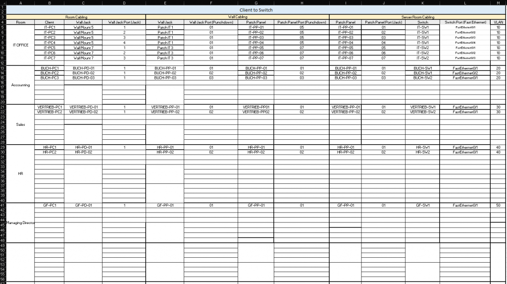
The example tables below clearly illustrate both end-user (client) cabling and the backbone-side connections between switches (switch-to-switch) and between switches and servers (switch-to-server).

9) Testing and commissioning: don’t walk away right after installation
After installation, the final step should be testing. Saying “it’s done” without testing is risky. During commissioning, check these in order:
- Physical link tests (link lights, cable tester)
- DHCP distribution and correct scope (IP/mask/gateway/DNS)
- VLAN isolation (verify guest network cannot access internal resources)
- Internet access and DNS resolution
- Wireless coverage and roaming tests
- Redundancy behavior tests if present (STP, uplinks)
Especially when VLANs and security rules exist, it’s not enough to say “it works.” You need to say: “It works within the correct boundaries.”
10) Closing: planning is more valuable than the cable
In a network infrastructure project, pulling cables is the visible work. But real value comes from planning. When proper planning, proper cabling, and proper documentation come together, the network becomes much easier to manage for years. Adding devices becomes easier, troubleshooting gets faster, and security policies can be applied more clearly.
Once you learn network planning properly, it moves you from “someone who installs” to “someone who designs infrastructure.” And in system integration work, that difference matters a lot—because good infrastructure is built not only for today, but with tomorrow in mind.